
Home Extension Drawings Explained: Plans, Elevations, Sections
Updated: 2 days ago
A standard home extension drawing pack includes existing drawings (plans and elevations of the house as it currently is), proposed drawings (plans and elevations showing the extension), sections (cuts through the building showing construction), construction notes, and three context plans: location, site and block. Together they cover everything planning officers, building control inspectors and contractors need to assess and build the extension.
The pack is what the council decides planning on, what building control checks the construction against, and what your builder prices and builds from, so if it's thin or wrong, every stage after it goes slower. Below we go through what each drawing shows, using drawings from a single storey rear extension, and then what changes for a double storey extension. If you'd rather have one team handle the drawings, approvals and build, that is how we run home extensions in Kettering and across Northamptonshire.
What drawings do you need for a home extension?
The exact pack depends on the council, the size of the extension, and if you are going through full planning permission or relying on permitted development. As a rule, you'll need:
Existing drawings. Plans and elevations showing the house as it stands today.
Proposed drawings. Plans and elevations showing the house with the extension built.
Sections. Vertical cuts through the building showing how it's put together.
Site plan. Your property and its immediate surroundings, usually at 1:200 or 1:500.
Location plan. A wider plan, usually at 1:1250, showing the property in context.
Block plan. The position of buildings within the site boundary.
Construction notes. Technical specifications for materials, foundations, insulation, drainage and so on.
Existing drawings
Existing drawings show the house as it currently stands. They're produced from a measured survey, where the designer or a surveyor visits the property and records every wall, window, door and ceiling height. A survey usually takes half a day on site.
Most planning applications require both existing and proposed drawings side by side, so the council can see exactly what's being changed. Existing drawings usually include:
Existing floor plans, one for each storey
Existing elevations, one for each face of the property (typically four)
Existing sections, if the project affects the structure significantly
Skipping or skimping on existing drawings is a common reason for planning applications being returned as invalid. The council needs the existing condition to assess the impact of the proposal.
Proposed plans and elevations
Proposed plans and elevations are the drawings most homeowners picture when they hear "extension drawings". They show the house as it will look once the extension is built.
The proposed ground floor plan shows the new layout: where the walls go, where doors and windows are positioned, where the kitchen, dining or living spaces sit. The elevations show each face of the property with the extension included, from the rear garden, from each side, and from the front if affected.

The drawing above is from a single storey rear extension project. The plan (top left) shows the ground floor with the new extension added to the rear, including a rear entry hall with level access for wheelchair users. The rear elevation (top right) shows the back of the house with the new windows and roofline. The two side elevations show how the extension reads from either neighbour's side. Notes around the drawings flag the specific decisions: extension set back 100mm from the boundary fence, existing doors re-used, level access at the rear, existing inspection chamber relocated.
Planning officers spend most of their time on the proposed plans and elevations. They want to see scale, massing, materials, and impact on neighbours. These drawings carry the weight of the application.
Sections and construction notes
Section drawings cut vertically through the building. They show how the floor, walls, ceiling and roof are built, and how each layer connects to the existing structure. A good set of sections demonstrates that the extension will meet current building regulations: insulation thicknesses, foundation depths, drainage routes, structural connections.
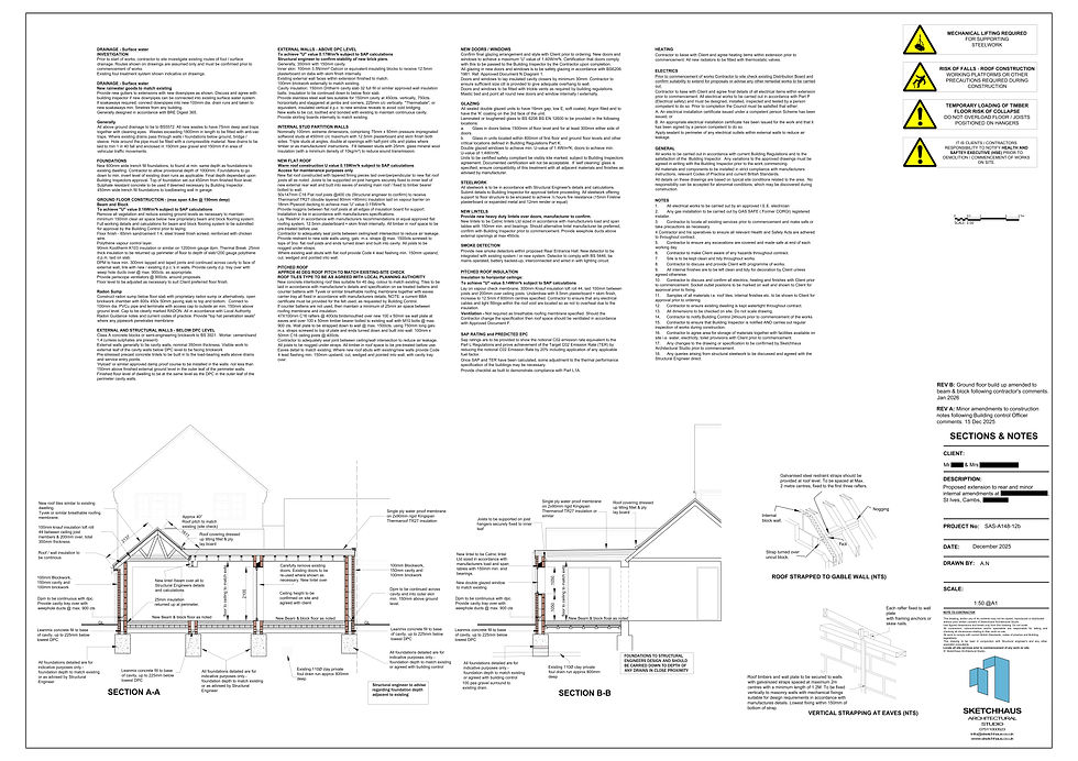
The drawing above shows the sections and construction notes from the same project. Section A-A and Section B-B cut through different parts of the extension, showing the foundation depths, cavity wall construction, insulation layers, roof build-up, and connection to the existing house. The notes column on the left specifies every material and standard the build has to meet, from the 150mm cavity insulation in the external walls, to the 300mm of loft roll insulation in the pitched roof, to the radon sump below the floor slab.
Building control inspectors live in these drawings. They want to see that every part of the extension meets the relevant regulation: Part L for energy efficiency, Part A for structure, Part H for drainage, Part K for safety glazing.
This level of detail is also what separates a buildable drawing from a pretty one. If the sections aren't right, the builder either has to stop and settle decisions on site, or the work fails inspection later.
Site plan, location plan and block plan
These three context drawings are needed for any planning application. They show the council where your property sits and what surrounds it.
Location plan. Usually at 1:1250 scale. Shows your property edged in red, with at least two named roads visible. Sourced from Ordnance Survey or a paid plan supplier.
Site plan. Usually at 1:200 or 1:500 scale. Shows your property and the immediate area in more detail, with the proposed extension footprint indicated.
Block plan. Shows the buildings within your site boundary and their relationship to one another. Often combined with the site plan on smaller projects.
Most councils require all three, plus the proposed and existing drawings, before they'll validate an application. Missing any of them sends your application back to the start.
Planning drawings vs building regulation drawings
Planning drawings are produced for the planning application. They focus on appearance, scale, impact on neighbours, and local planning policy. They're usually drawn at 1:100 or 1:50.
Building regulation drawings are produced for building control. They focus on technical compliance: structure, insulation, fire safety, drainage, glazing. They're usually drawn at 1:50 with detailed sections and construction notes.
Most extensions need both. The planning drawings come first, and the building regulation drawings follow once planning is granted, although preparing both together avoids redesigning details twice. A householder planning application has a statutory 8-week decision period from validation, and building regulation approval can run in parallel.
What changes for a double storey extension?
A double storey extension needs the same pack, plus more structural and fire detail, because the upper floor changes how loads travel through the house and adds a new escape route to design.
Three things to know:
Planning. Many two-storey extensions need a planning application, but not all. Under permitted development in England, a two-storey rear extension can extend up to 3 metres beyond the original rear wall, must be at least 7 metres from the rear boundary, must match the existing roof pitch where practicable, and upper-floor side windows must be obscure-glazed and fixed below 1.7m. Two-storey side extensions always need an application. Check the Planning Portal for the full limits.
Structural calculations. A structural engineer (not the architect or builder) calculates the steels, lintels, foundations and any new floor structure. Building control won't approve the scheme without them.
Sections and fire detail. The sections need to show the upper floor build-up, fire separation, and how the new rooms connect to the existing stairs and escape routes.
Our guide to the two storey extension covers the design and build side in more detail.
How long do extension drawings take, and what do they cost?
For a typical extension, allow 2 to 3 weeks for the survey and proposed drawings, 8 weeks for a planning decision once the application is validated, and 2 to 4 weeks for the building regulation drawings. That is roughly three to four months from first sketch to approvals, longer if the council asks for amendments.
As a rough UK guide to fees:
Architect (planning and building regs drawings): often 8 to 12% of construction cost
Architectural technologist or designer: often 2 to 5% of construction cost
Structural engineer: typically £600 to £1,500 for a standard domestic job
Householder planning application fee in England: £528
Building control fees: set by your council or approved inspector, commonly several hundred pounds to over £1,000
Whether you need a full architect or a technologist depends on the project; our post on whether you need an architect for a small extension goes through that choice. Whoever you use, ask to see drawings for projects that have actually been built and passed planning and building control.
If you're planning an extension in Kettering, one of our house extensions in Corby or anywhere else in Northamptonshire, and want one team to handle the drawings, planning and build, we can take it from survey to completion.

Comments